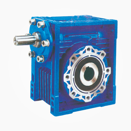
RV WORM GEAR
SPEED REDUCER
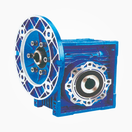
RV
RV..VS
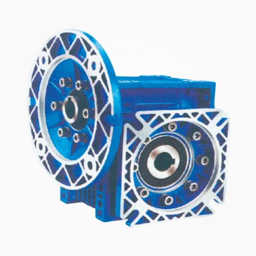
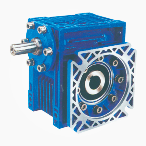
RV..F2
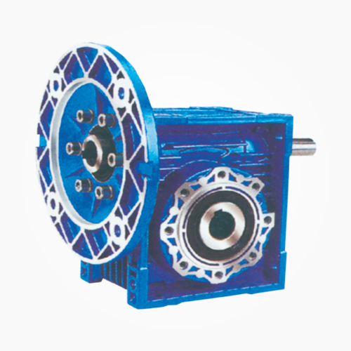
RV-S
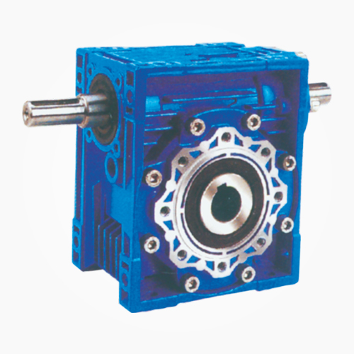
RV-SS
RV-SF
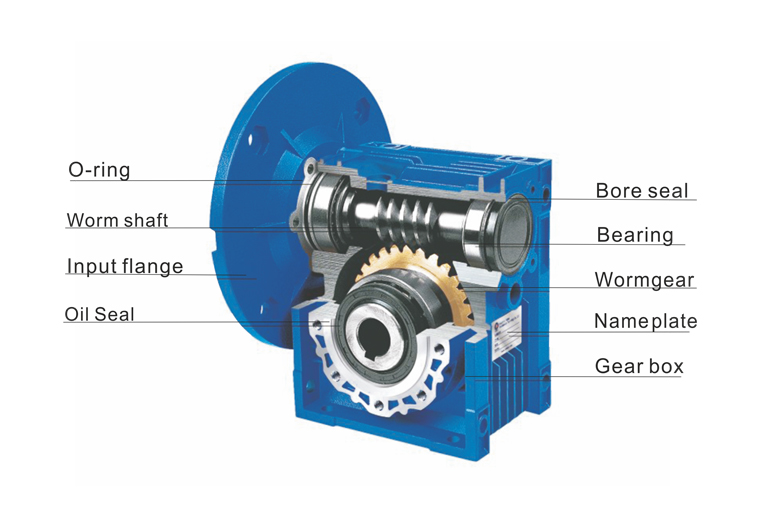
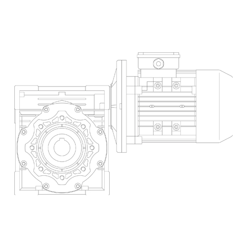
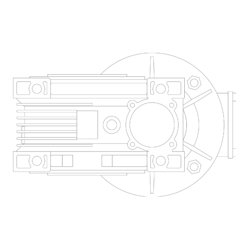
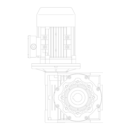
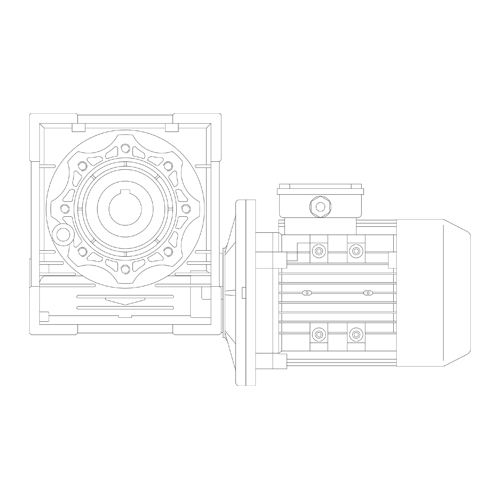
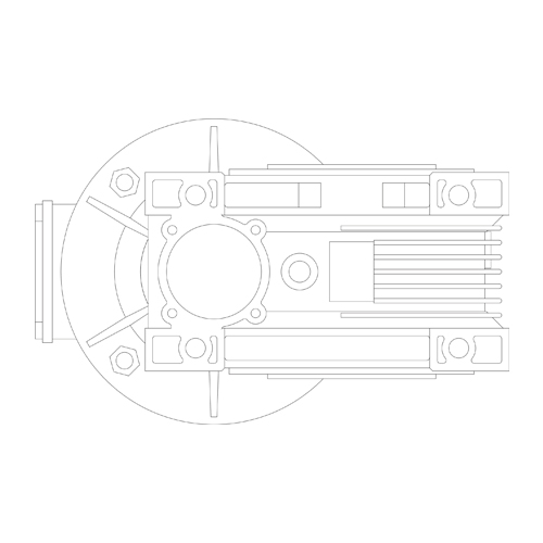
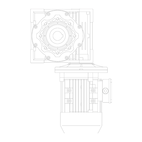
Prouduct Structure & Single Step Mounting Positions
Model Selection
Please understand the following at first in order to select the model of RVB Worm-gear speed reducer properly :
1. Load Condition.
2. Speed scope or ratio in application.
3. Working condition and environment.
4. Installation space.
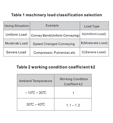
Define working in condition Coeffiecient k1 and revise coefficient k2.
1. Ensure machinery load types A,B,C according to table 1.
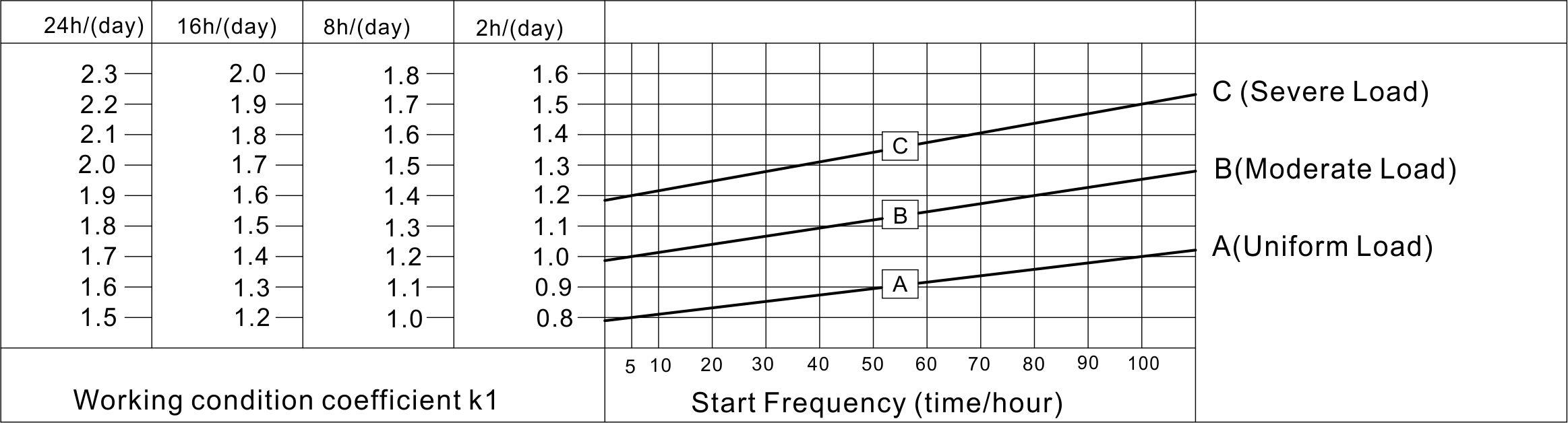
2. Get the working condition coefficient k1 from diagram 1 according to turning ime(hour/day) and start frequency (times/hour).
3. Inspect working condition and select coefficient k2 from table 2.
Diagram 1 working condition coefficient k1
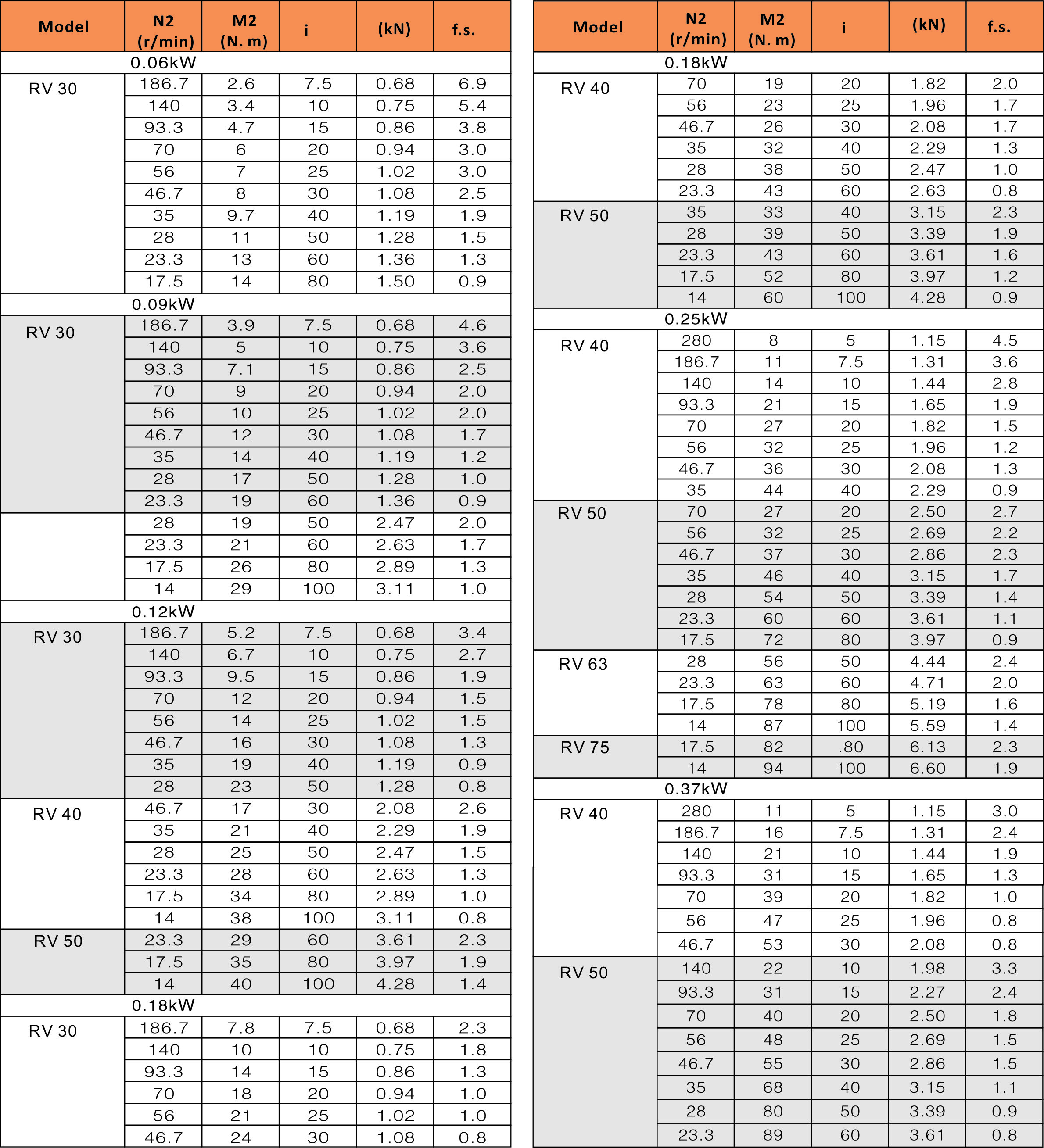
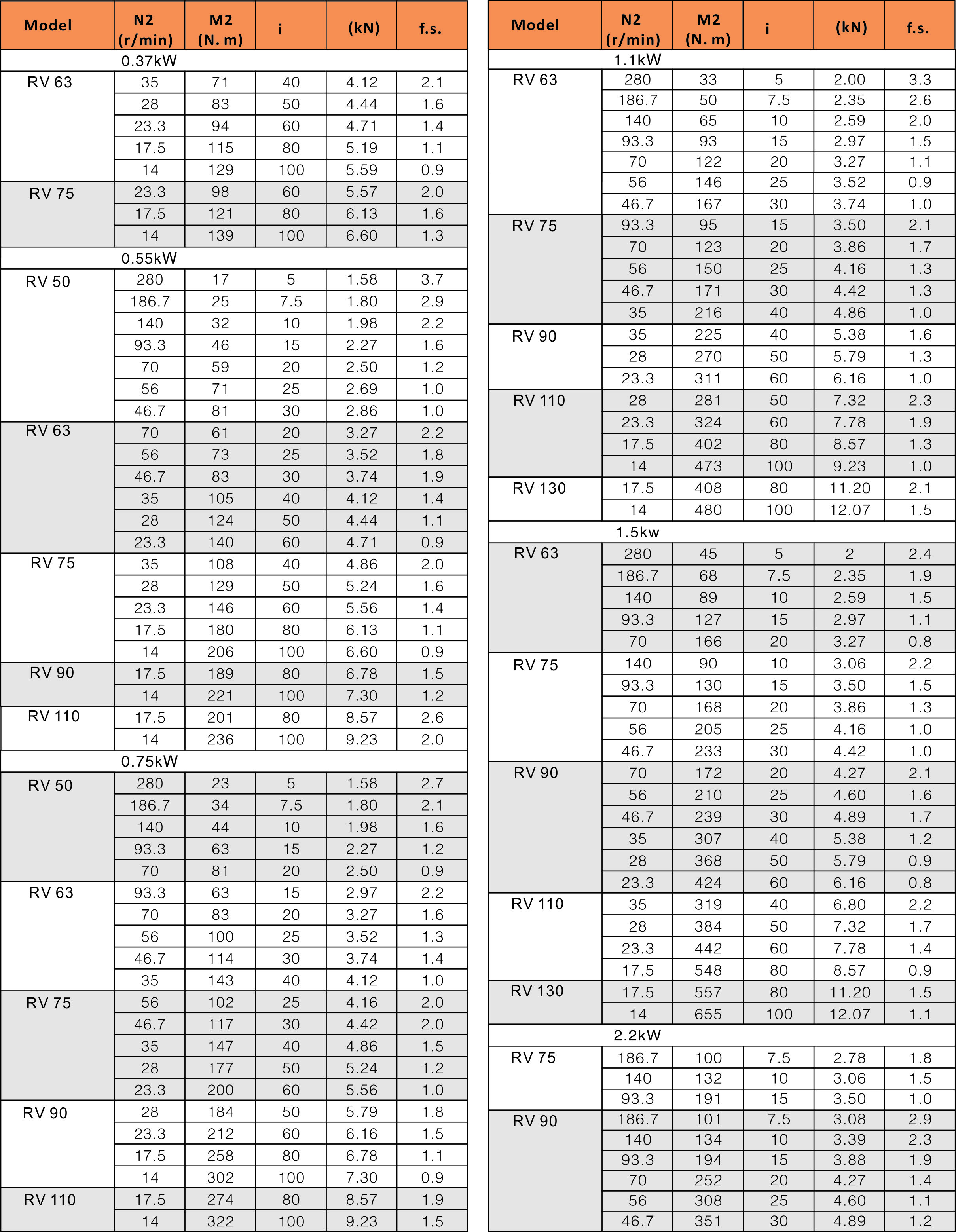
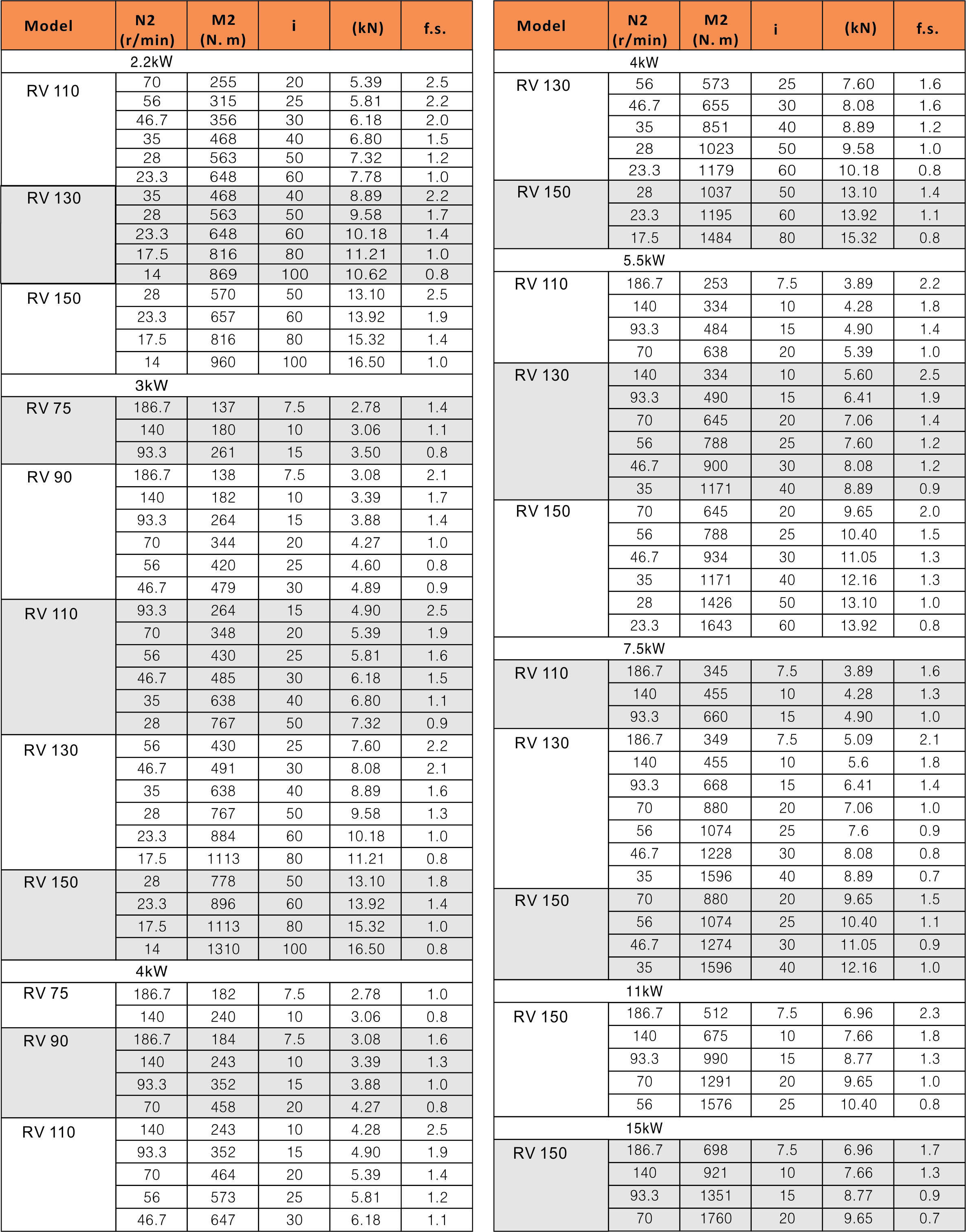
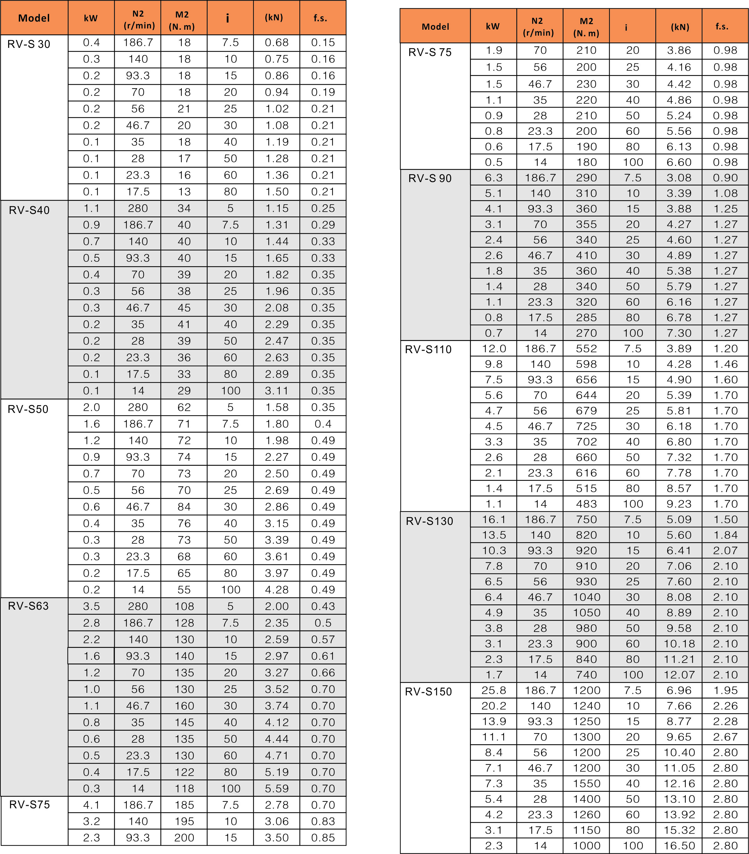
Parameter Selections
RV Single Reducer(flange input,input speed is 1400r/min) / (matched with 4 poles motor)
RV-S (1400r/min)
RV Singles Step Reducer(shaft extend input,input speed is 1400r/min)
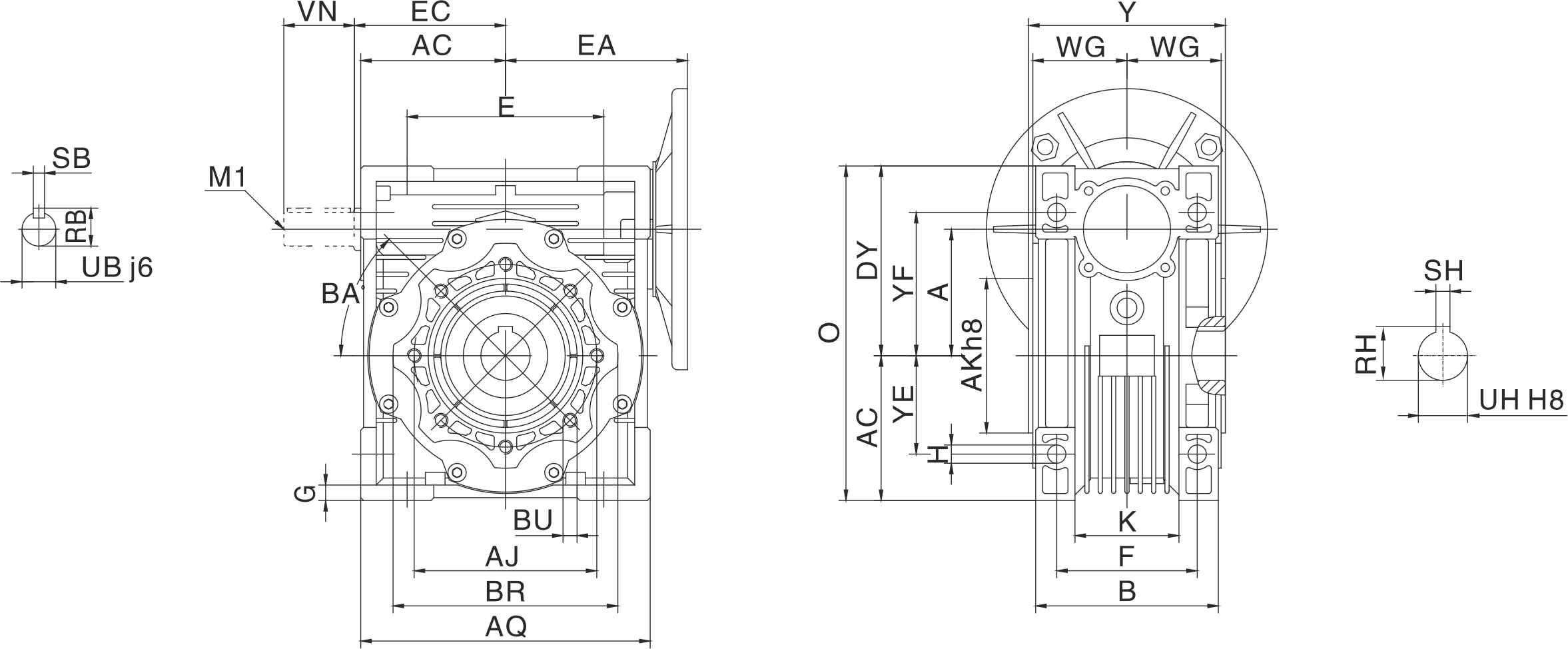
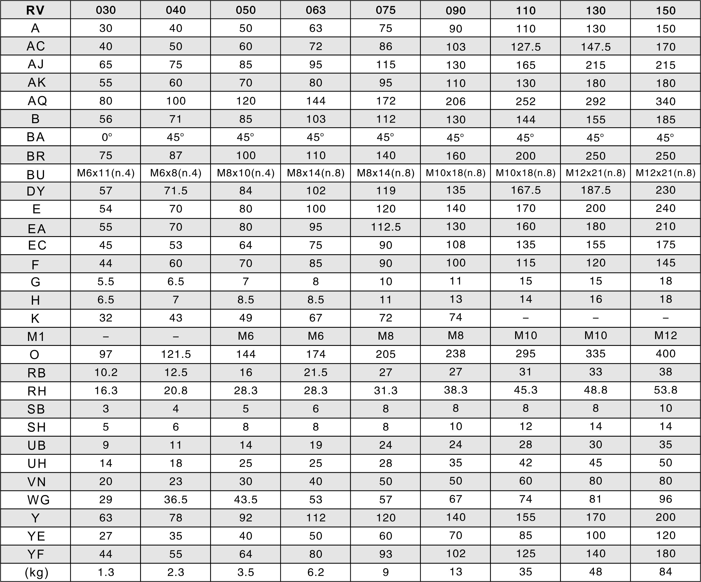
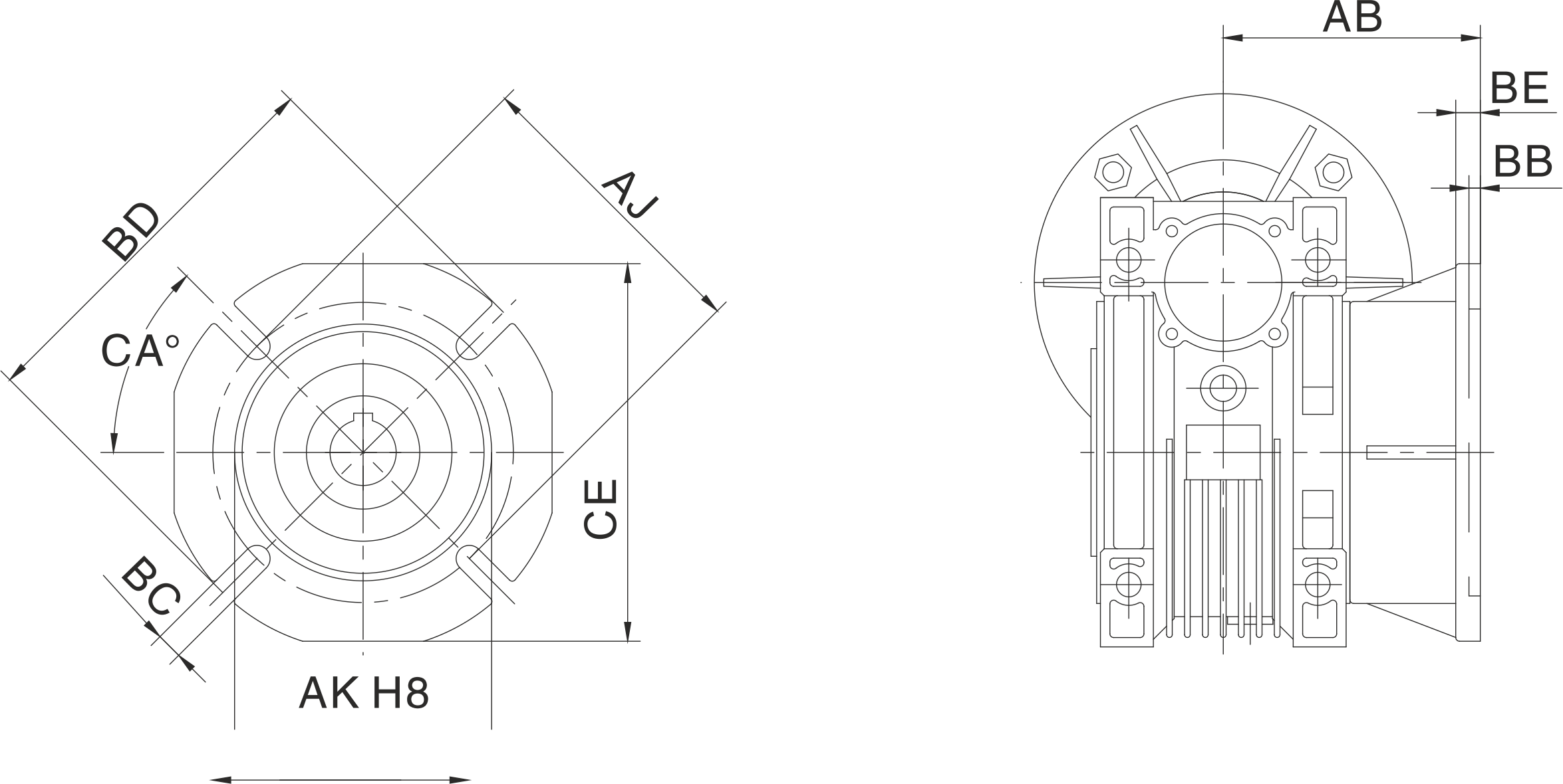
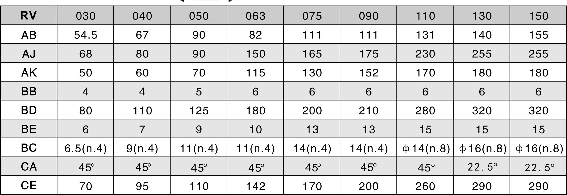
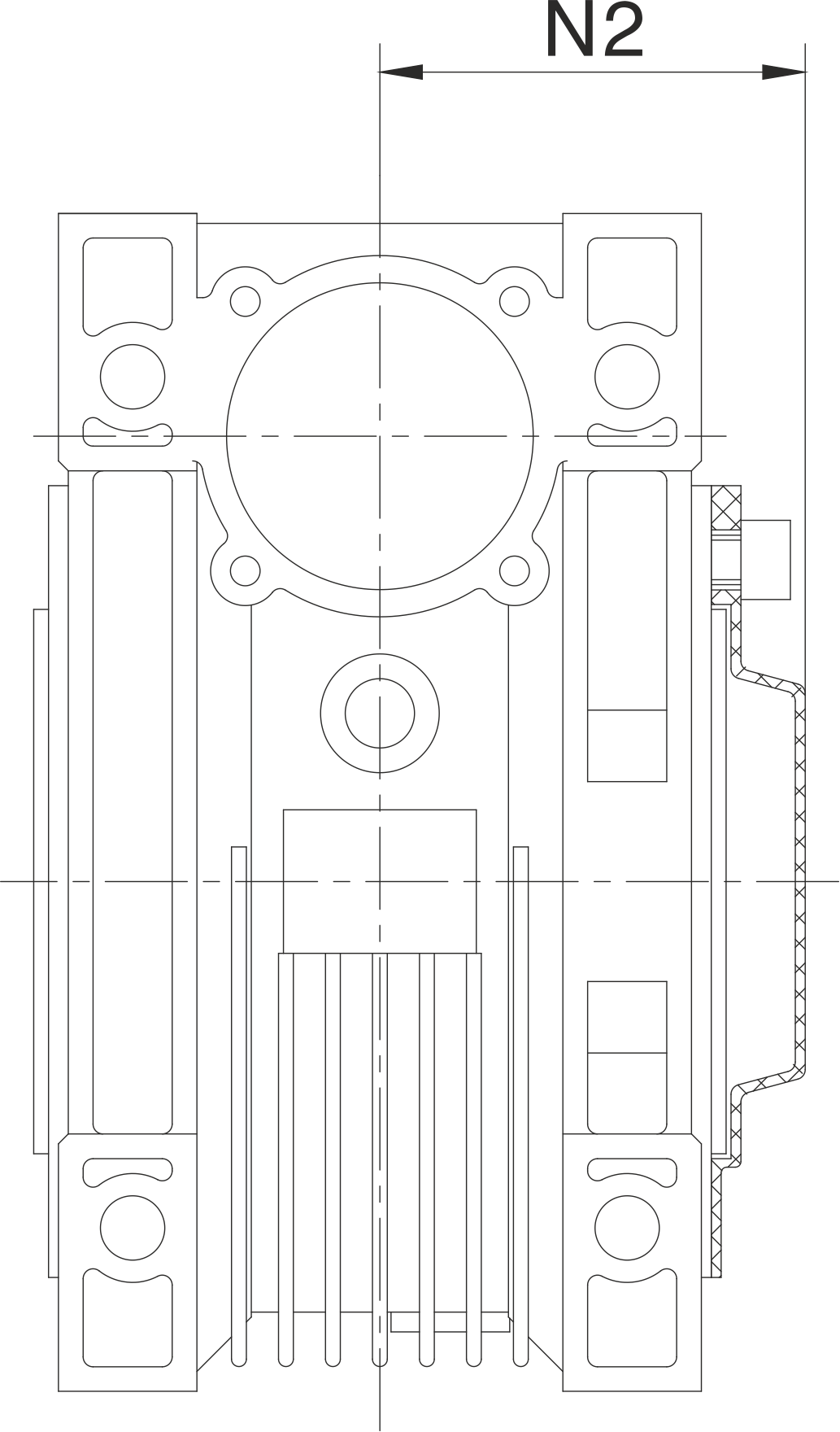
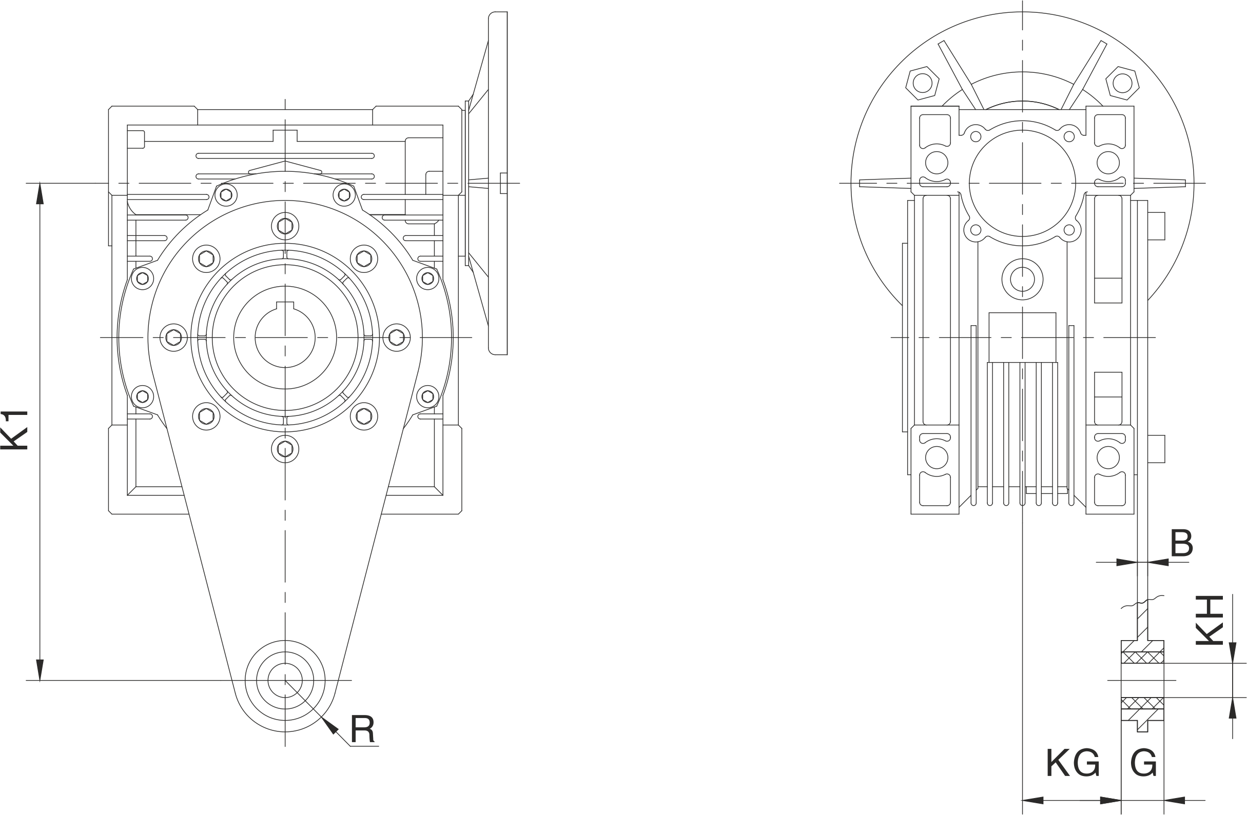
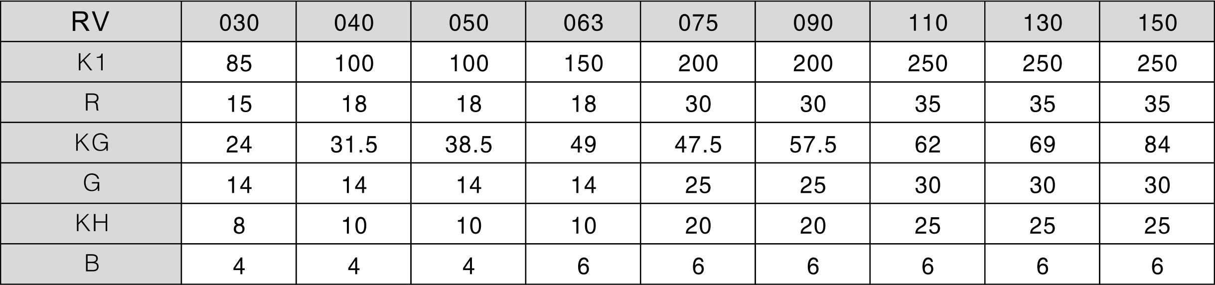
Mounting Dimensions
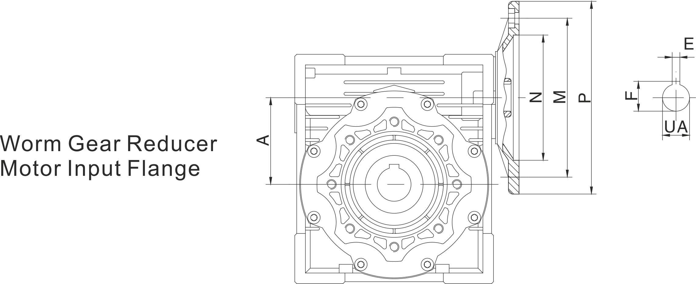
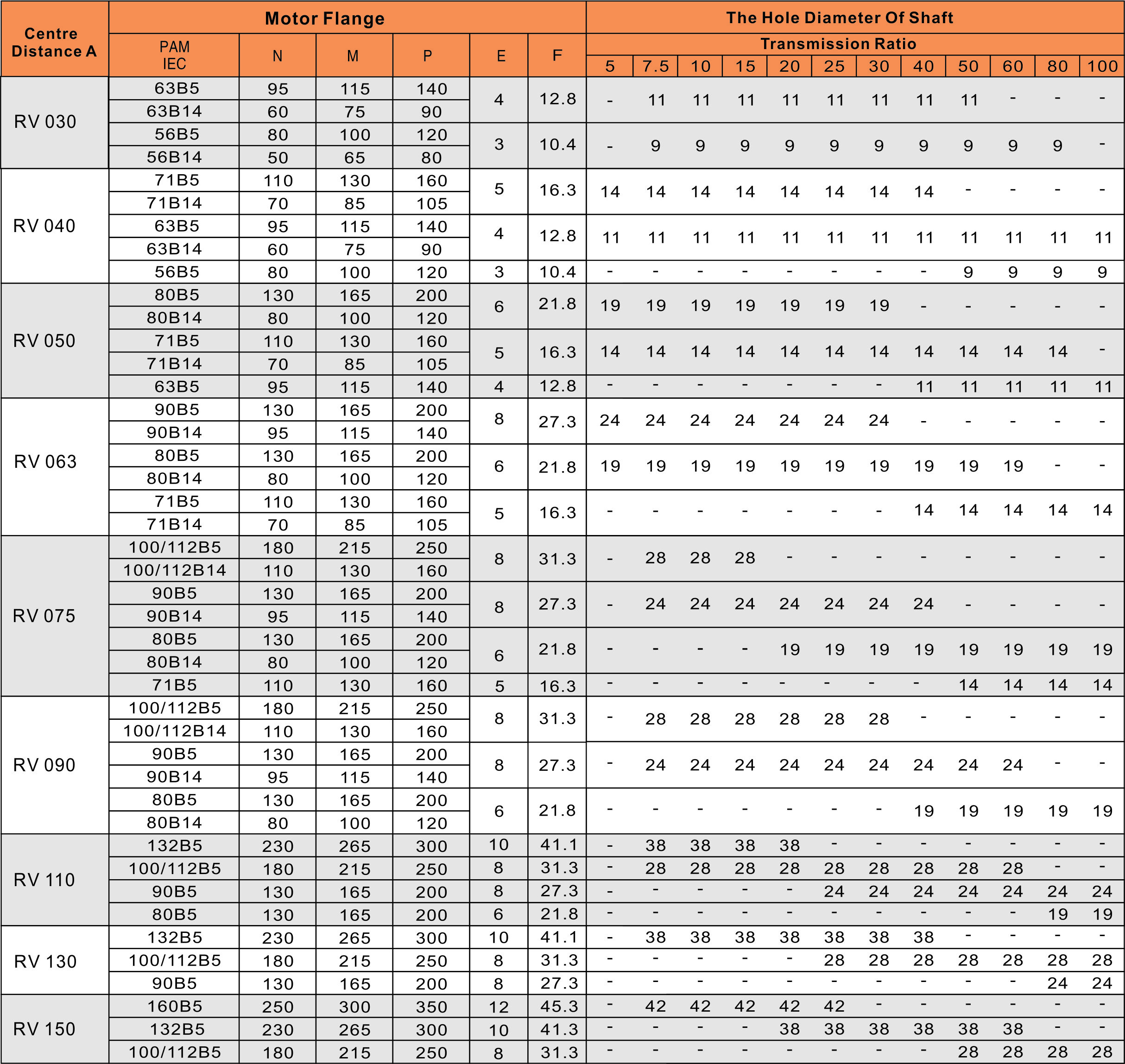
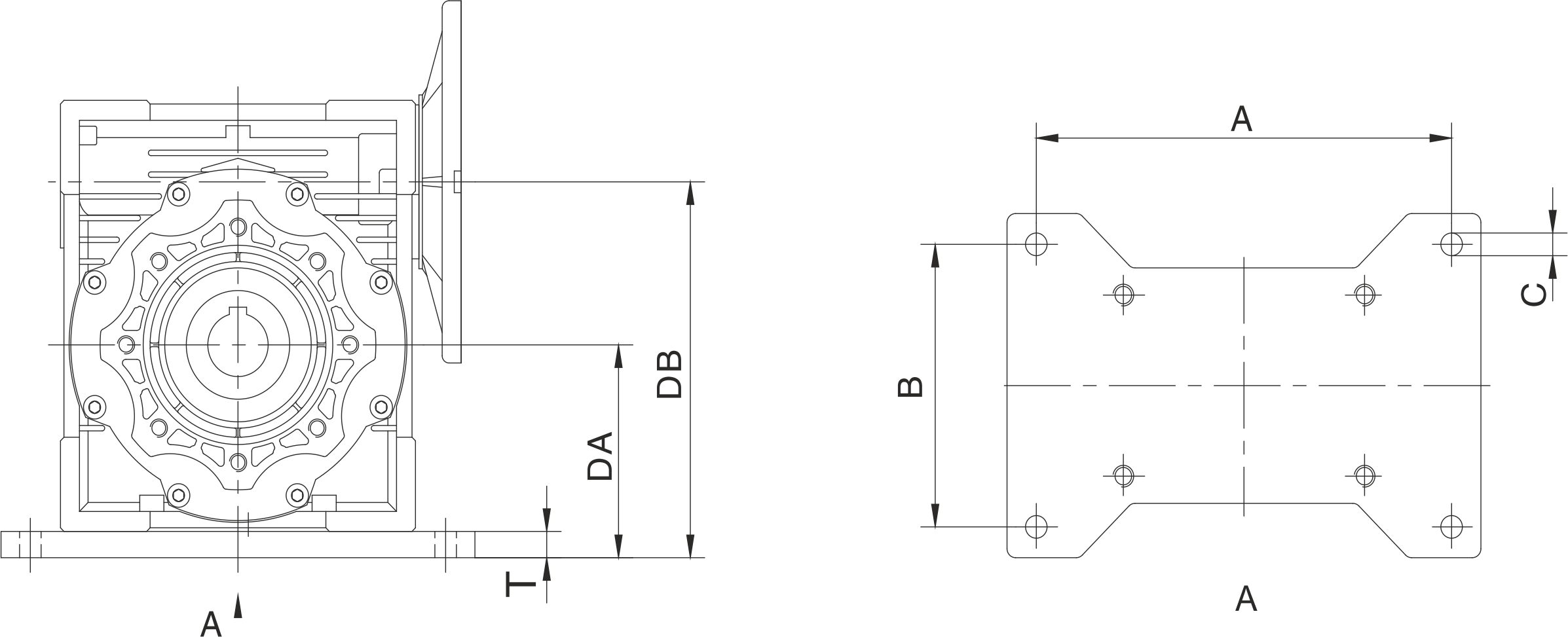
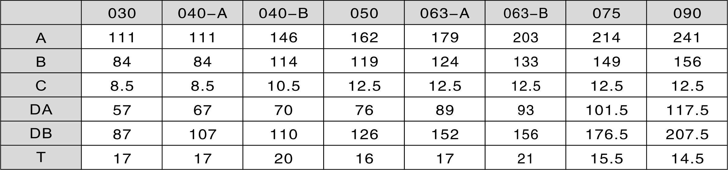
RV Mounting Dimensions
Output Flange Mounting Dimensions
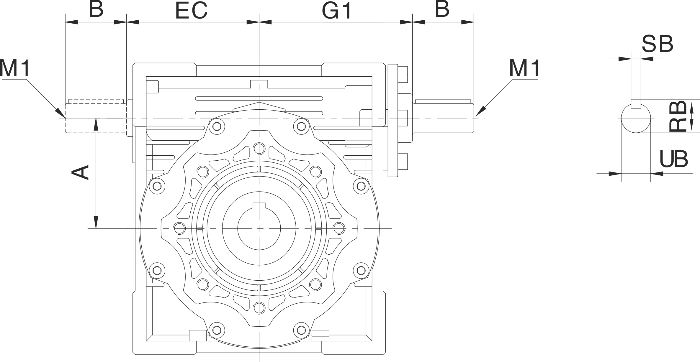
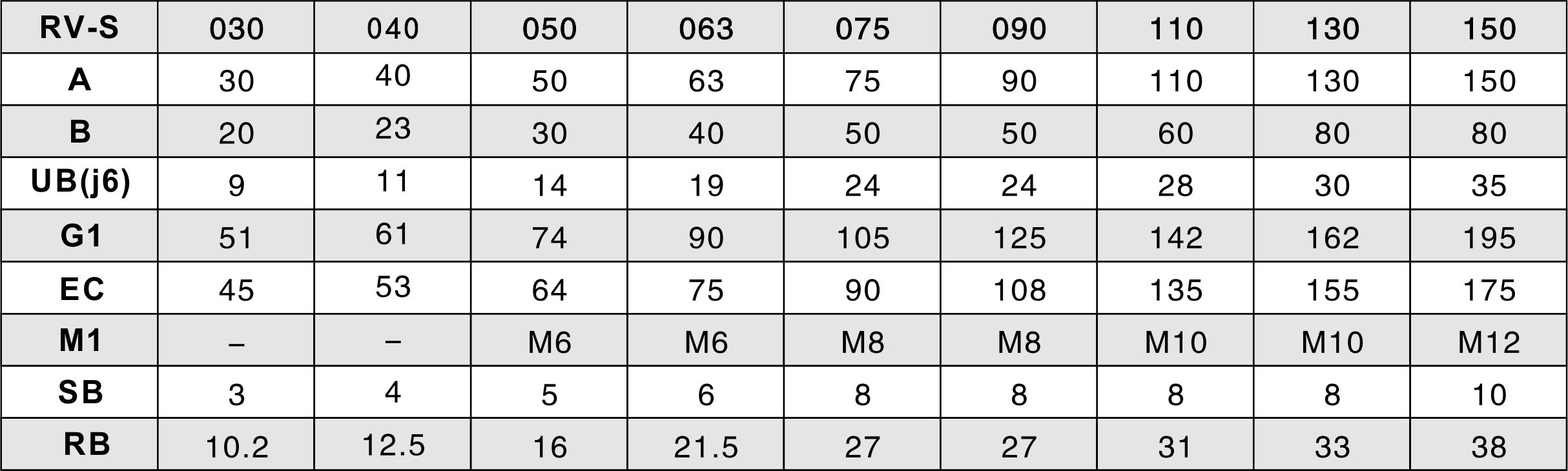
R V -S Input Shaft Dimensions
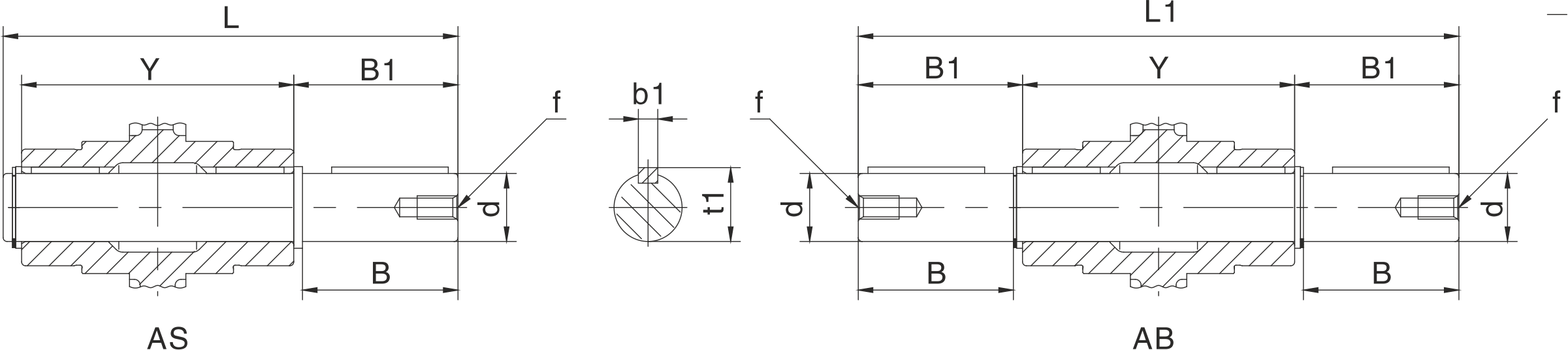
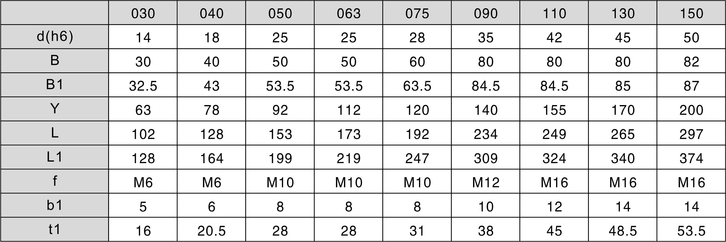
Accessories (AS) (AB) Single & Double output shaft Dimensions
( C ) Base Plate
( D ) Protective Cover

( E ) Torque Arm
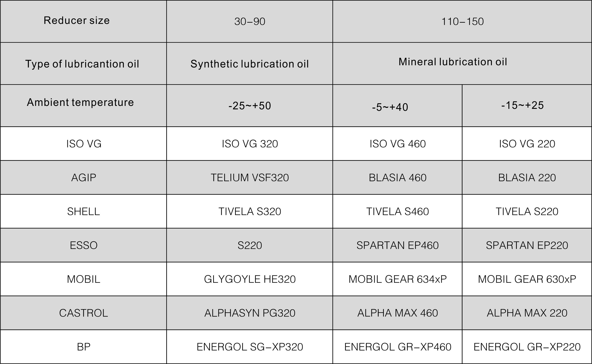
Lubricant
Lubrication Oil Chosen Table
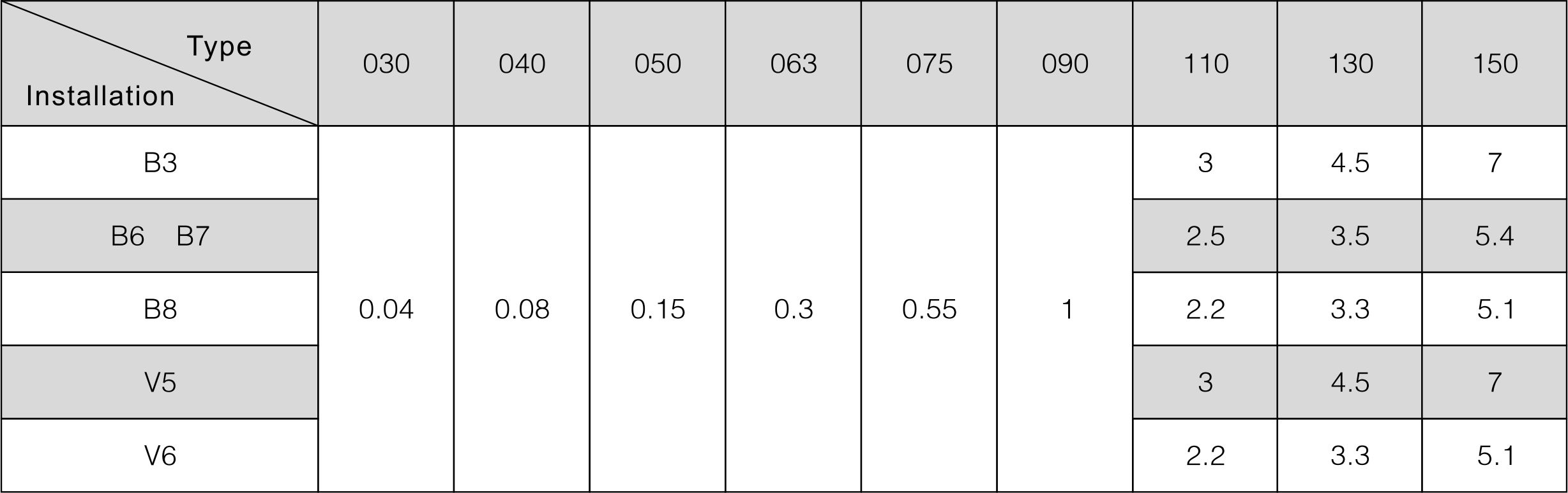
Adding Capacity of Lubrication Oil
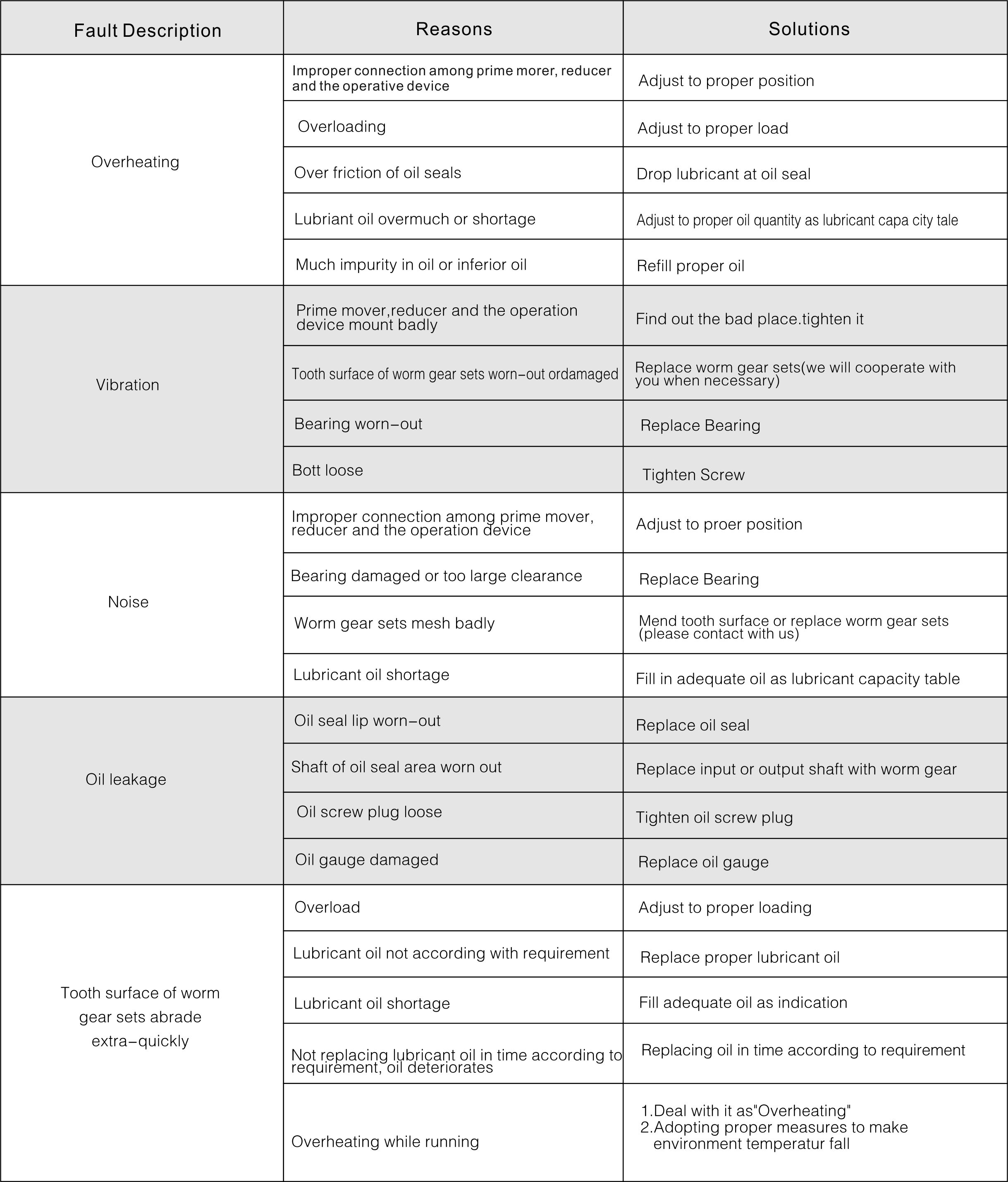
Malfunctions Analysis